What SLS 3D Printing Quality Actually Looks Like
Datasheets specify accuracy. Marketing photos show perfect surfaces. But when you are deciding whether SLS can replace injection molding or CNC machining for your application, you need to know what comes out of the printer — with measurements, not adjectives.
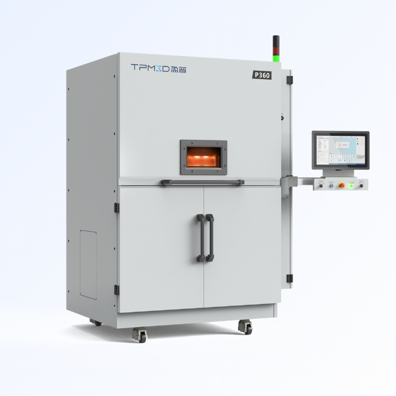
This article presents SLS 3D printing quality data from actual test parts printed on the TPM3D P360. The parts were printed in Precimid1172Pro GF30 BLK (glass beads filled PA12) and Precimid1172Pro BLK (PA12) at 0.12mm layer thickness. Every claim is backed by a measured number or a photographed surface.
We cover three dimensions of quality: dimensional accuracy, surface finish, and feature resolution — including where the process excels and where it has limitations you should design around.
Dimensional Accuracy: Measured Deviations
How We Tested
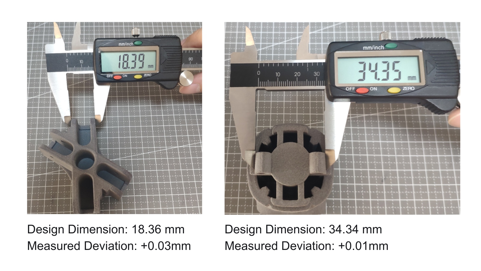
Reference test parts with known design dimensions were printed and measured with calipers. The deviations below are the difference between the CAD dimension and the actual printed dimension, in both the XY (horizontal) and Z (vertical) directions.
Horizontal Dimensions (XY Plane)
| Design Dimension (mm) | Measured Deviation | What This Means |
|---|---|---|
| 18.36 | +0.03mm | Within 0.2% of design |
| 34.34 | +0.01mm | Within 0.03% of design |
On horizontal dimensions, the P360 holds tolerances well under ±0.05mm for parts in the 18–35mm range. The slight positive bias (parts print marginally larger than design) is consistent and predictable — it can be compensated in CAD if needed.
Vertical Dimensions (Z Axis)
| Design Dimension (mm) | Measured Deviation | What This Means |
|---|---|---|
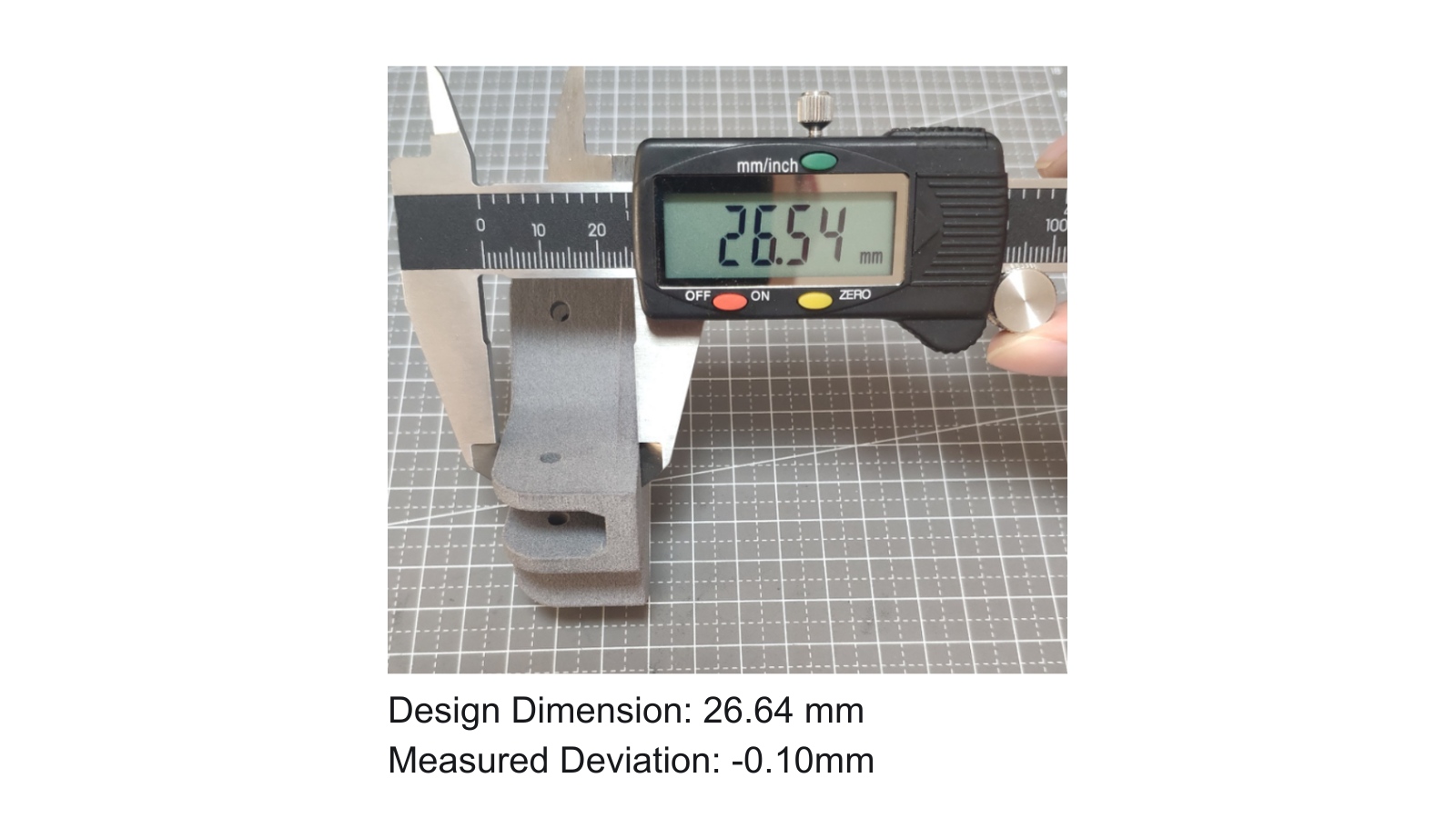
| 26.64 | -0.10mm | Less than the height of a 0.12mm layer |
Vertical deviation is larger than horizontal — this is expected in all layer-based processes. The -0.10mm deviation on a 26.64mm feature translates to less than the height of a single 0.12mm layer.
Thin Walls
| Wall Design Thickness (mm) | Measured Deviation | Notes |
|---|---|---|
| 0.50 | +0.02mm | Excellent — 0.5mm walls print accurately |
| 0.66 | +0.04mm | Consistent positive bias |
Thin walls at 0.5mm are printable with only +0.02mm deviation. This is a meaningful result: 0.5mm walls are at the lower limit of what SLS can reliably produce, and the P360 handles them without closing up or distorting.
Surface Finish: What You See Out of the Printer
Top and Bottom Surfaces (Flat)
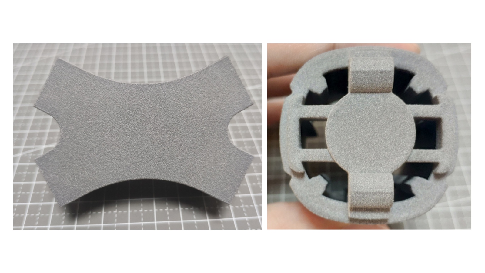
Test parts printed on the P360 show smooth, flat surfaces with laser scan lines that are not visibly obvious. The surface is uniform and matte — no pitting, no blistering, no visible defects.
This is the result you want for visible surfaces of functional parts. The surface is smooth enough that it does not require sanding for internal or structural applications. For customer-facing surfaces, media blasting or vapor smoothing will produce a uniform satin finish in minutes.
Sidewalls
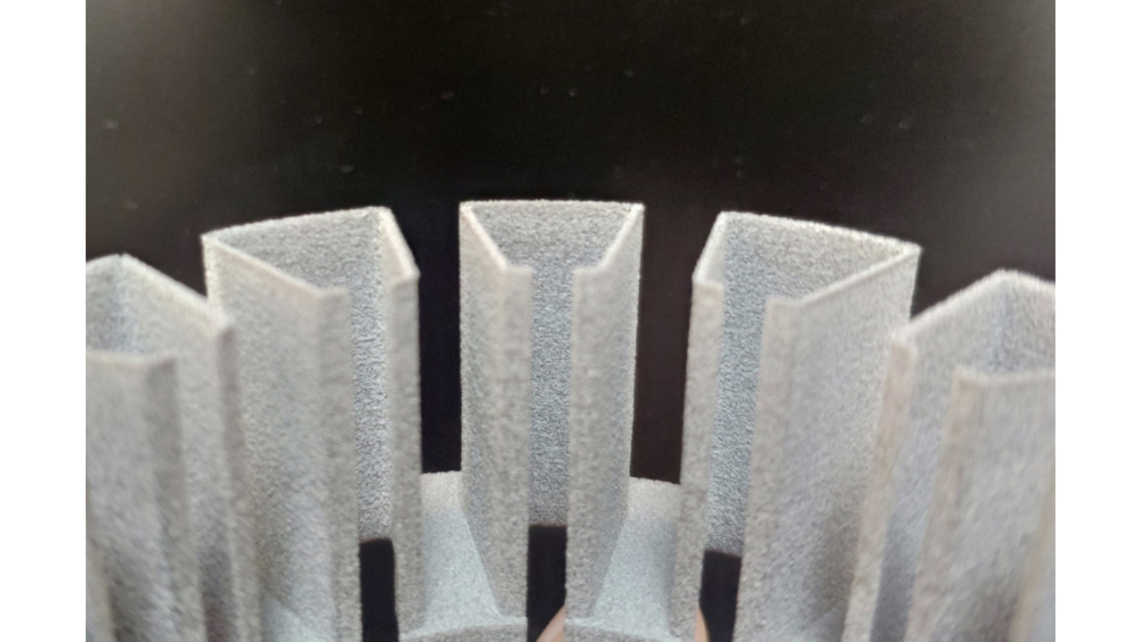
Sidewalls show minimal orange peel and layer lines that are not obvious. Orange peel — a textured, rough appearance on vertical surfaces — is a common SLS defect caused by uneven powder spreading or thermal inconsistency. On these shown P360 printed parts, it is essentially absent.
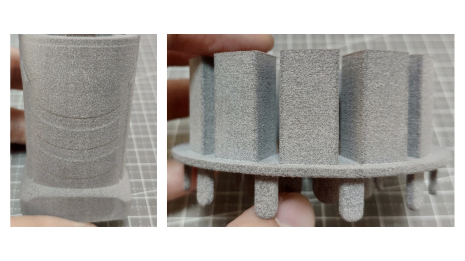
The layer lines at 0.12mm layer thickness are visible only if you look closely. On vertical walls, they appear as very faint horizontal striations. On angled surfaces (30–60° from horizontal), stair-stepping is more pronounced but still subtle.
Corners: Clean and Sharp
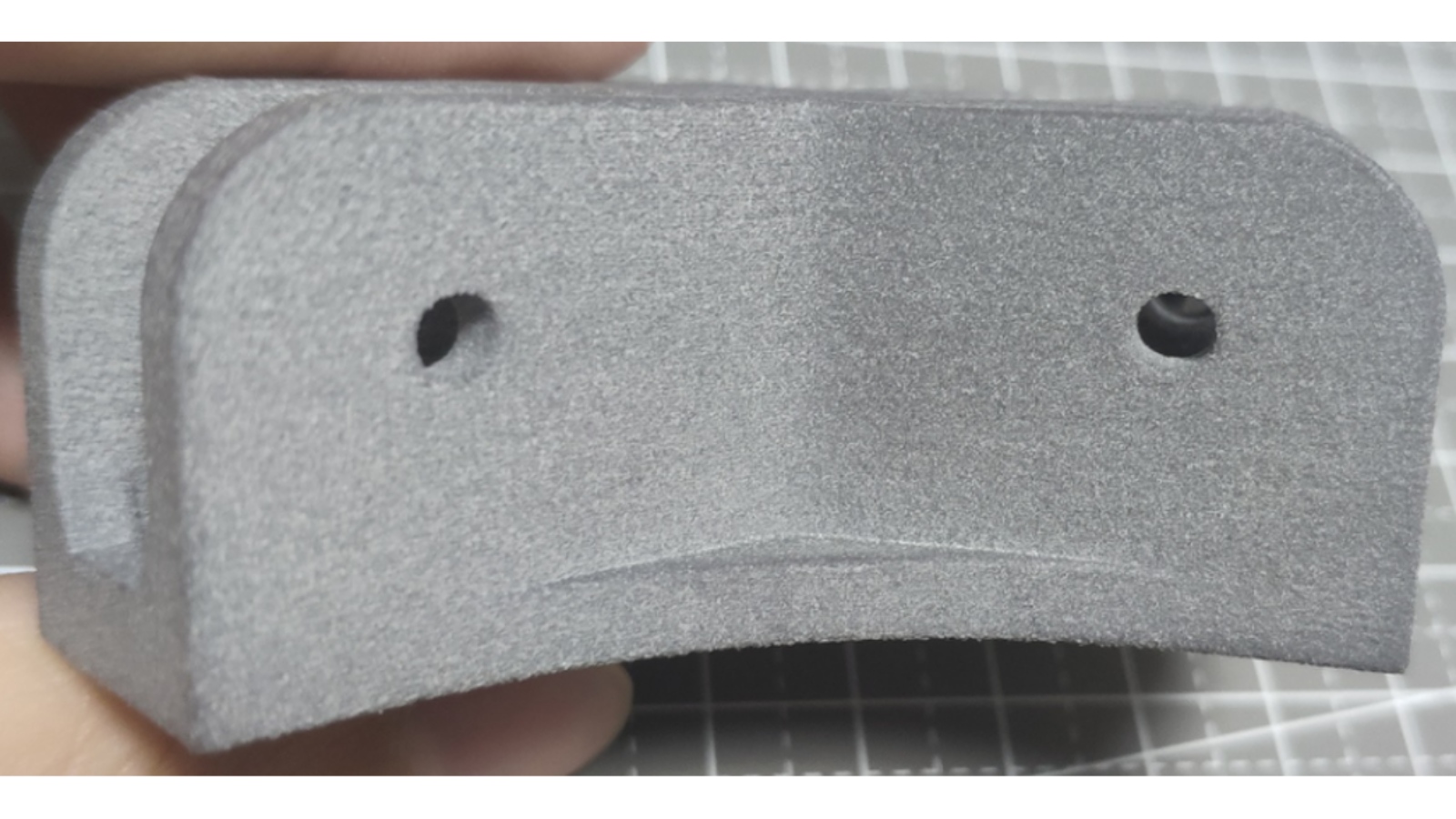
Frame corners on test parts showed no protrusion or bumping — including at sharp-angle corners. Corner protrusion is a common SLS defect where excess heat accumulates at direction changes in the laser path, causing material to bulge. Thanks to the efficient laser path planning and precise energy control of the TPM3D P360, the laser automatically compensates for energy when scanning around corners.
Why the Surface Quality Is Consistent
Two factors drive the smooth surface:
- Blade recoating system. The P360 uses a recoating blade (not a roller) to spread each powder layer. Blades produce a flat, even powder bed. Rollers can introduce vibration marks and static charge — both of which create surface defects.
- High laser absorption rate. The CO₂ laser achieves approximately 96% absorption with nylon powder. This means the laser energy goes precisely where it is aimed, with minimal thermal spread. The result is clean sintering without overheating surrounding powder — which would otherwise cause surface roughness and part growth.
Mechanical Strength: More Force to Deform and Break
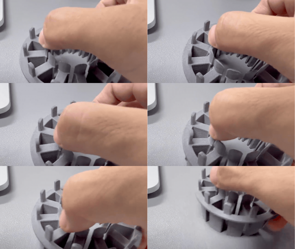
Test parts were subjected to manual bending and breaking force comparison. P360-printed parts required more force to deform and more force to fracture than the reference baseline. This indicates that the sintering process produces dense, well-fused material — not just on the surface, but throughout the part cross-section.
The CO₂ laser’s 96% absorption rate with nylon means that each layer is fully sintered, not partially fused. Full sintering produces higher density and interlayer bonding — which translates directly to mechanical performance.
Frequently Asked Questions
What is the dimensional accuracy of SLS 3D printed parts?
On the TPM3D P360, horizontal features in the 18–35mm range hold ±0.03mm. Vertical features show slightly more deviation — approximately 0.10mm on a 27mm feature.
How smooth is the surface of an SLS printed part?
SLS parts have a matte, slightly grainy surface out of the printer. On the TPM3D P360, flat surfaces are smooth with no visible laser scan lines, and sidewalls show no orange peel. At 0.12mm layer thickness, layer lines are faint. Media blasting or vapor smoothing produces a uniform satin finish in 10–15 minutes, and further post-processing can be performed according to requirements, e.g., vapor smoothing for a smooth, glossy surface.
Can SLS print thin walls?
Yes. The TPM3D P360 reliably prints walls as thin as 0.5mm with only +0.02mm deviation. Walls at 0.66mm show +0.04mm deviation. Below 0.5mm, results become less predictable.
Are SLS printed parts strong?
TPM3D P360 parts require more force to deform and break compared to FDM printed parts, indicating full sintering density. The CO₂ laser’s 96% absorption rate with nylon powder ensures complete fusion between layers.
Why do SLS parts have rounded edges?
The laser spot diameter (0.25mm on the P360) sets the minimum edge radius. Because the beam has physical width, sharp edges and chamfers print with a small radius. This is inherent to the laser sintering process. Post-machine if razor-sharp edges are required.
What layer thickness should I use for SLS printing?
The TPM3D P360 supports 0.06–0.20mm layer thickness, with 0.12mm recommended for most applications. At 0.12mm, the balance between surface quality, accuracy, and print speed is optimal. Thinner layers (0.06mm) improve surface finish but significantly increase print time.
Read more: