What Is SLS Rapid Prototyping?
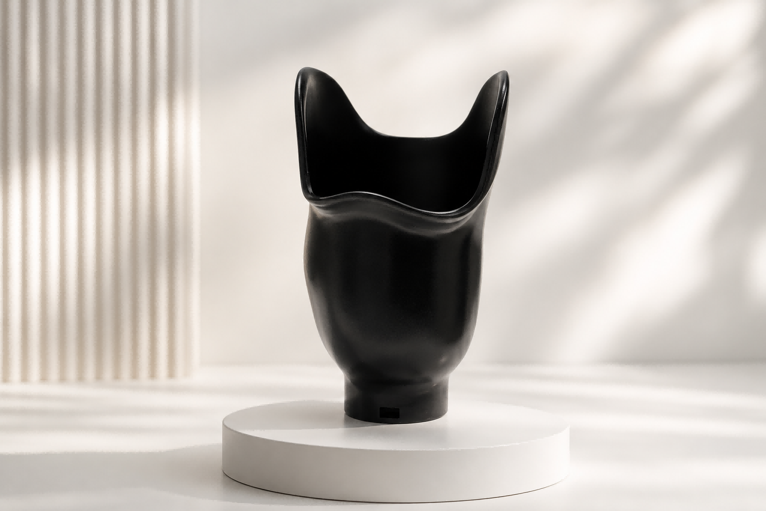
Selective Laser Sintering (SLS) is an additive manufacturing process that uses a laser to fuse polymer powder layer by layer into solid parts. In rapid prototyping, SLS offers something unique: prototypes that don’t just look right — they work right. The resulting parts are dense, isotropic, and durable enough for functional testing, not just visual review.
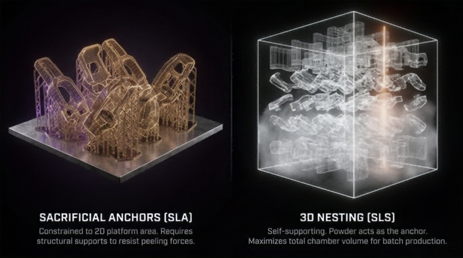
Unlike other 3D printing methods that produce weak inter-layer bonds or require support structures, SLS builds parts suspended in a powder bed. That means:
- No support removal. No support marks. No design compromise for printability.
- Mechanical properties that match the XY and Z axes — essential for load-bearing prototypes.
- The ability to pack multiple parts into a single build and let the powder handle clearance geometry.
The process is especially well-suited to nylon materials (PA11, PA12) and engineering thermoplastics (TPU, PP, PPS, PEEK), making it a practical bridge between early concept and production tooling.
Why SLS for Rapid Prototyping?
1. Functional Prototypes in Production Materials
SLS doesn’t require a separate “prototyping material” — you prototype in the same PA12 or PA11 powder that production parts will use. This means material behaviour, including:
- Tensile strength: 46 MPa for PA12 (TPM3D Precimid1172Pro, per ASTM D638)
- Elongation at break: 8–17% for standard PA12; higher-ductility grades available
- Flexural modulus: 1,280 MPa for PA12 (ASTM D790)
- Heat deflection temperature: 180 °C at 0.45 MPa for PA12 (ASTM D648)
- Chemical resistance and low moisture absorption versus FDM thermoplastics
…are identical between prototype and production part. No surprises during transition.
* All values above are from TPM3D Precimid1172Pro bright white PA12 powder datasheets. Different PA12 grades exist; always refer to the specific material’s certified datasheet.
2. No Support Structures
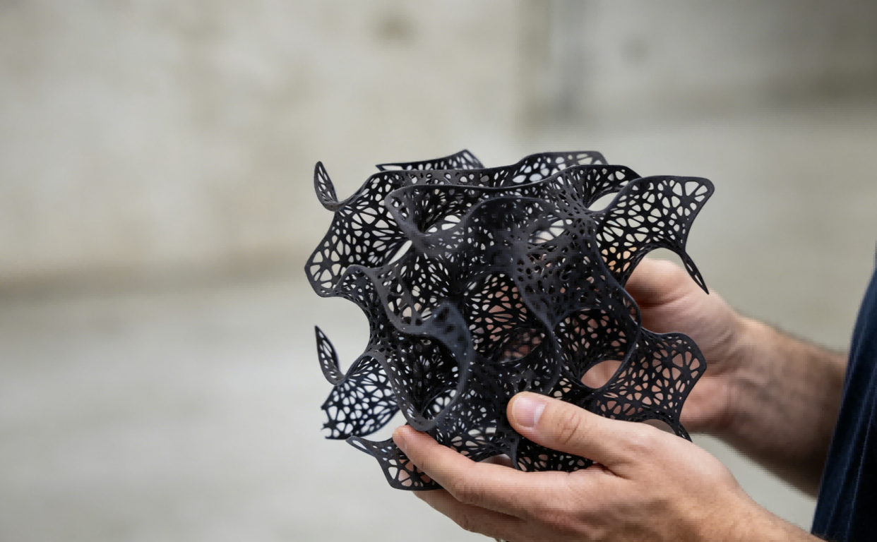
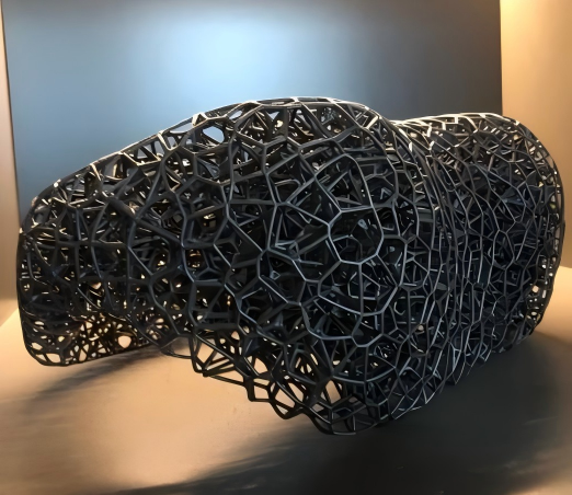
Because unsintered powder physically supports overhangs and cavities, SLS can produce:
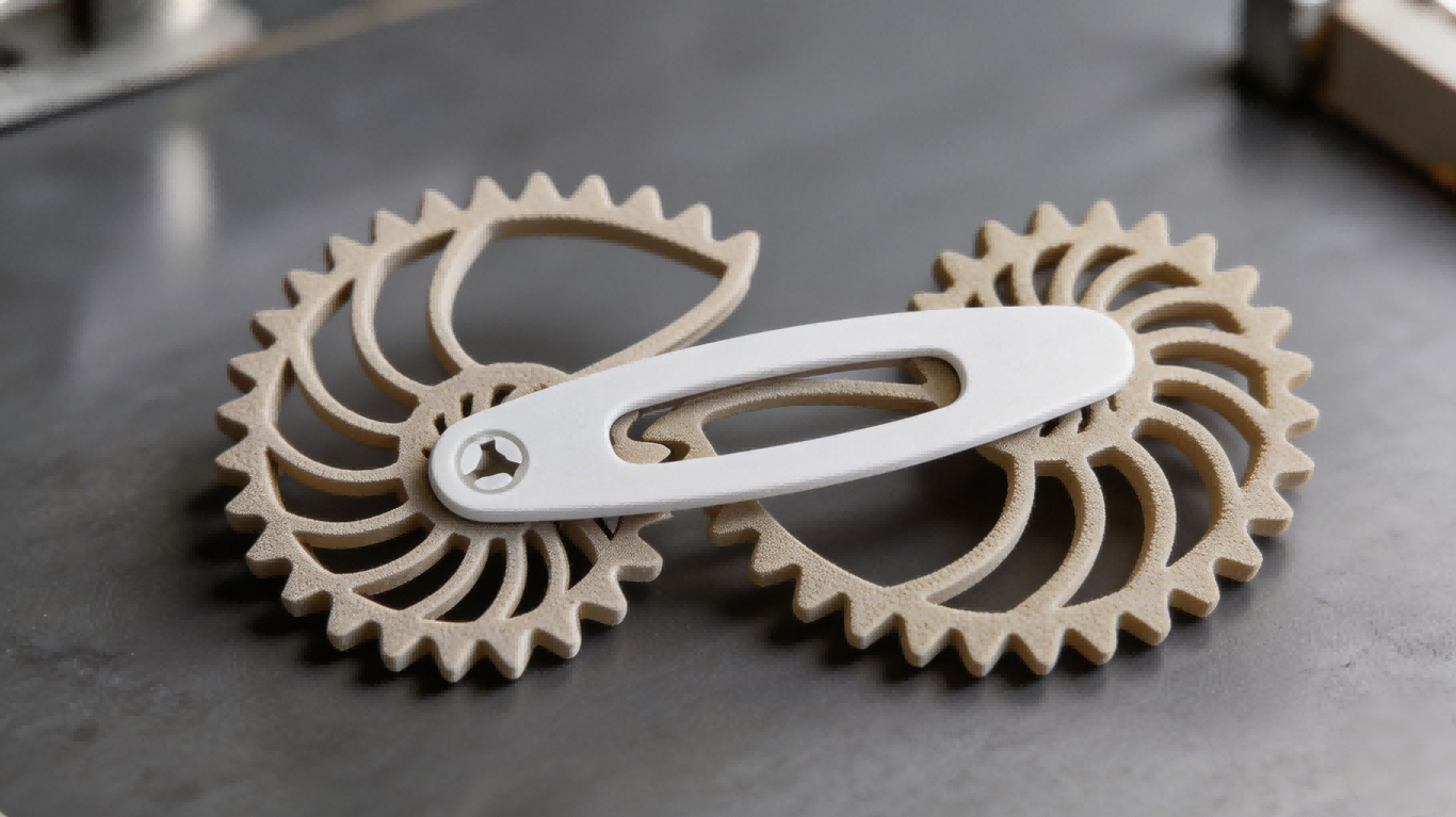
- Internal channels and lattice structures impossible by subtractive methods
- Living hinges and snap-fit features printed in the assembled state
- Complex organic geometries without support scarring
This freedom often eliminates assembly steps — a single SLS part can replace multiple CNC-machined or injection-moulded components.
3. Batch Production in One Build
A single SLS build chamber can contain dozens of different prototype designs simultaneously, as long as they fit within the build volume. The printer does not distinguish between one part and many — laser time is the primary cost driver.
| TPM3D Model | Build Volume (X×Y×Z) | Laser |
|---|---|---|
| CF200 (Compact Professional) | 200 × 200 × 320 mm | 30W fibre |
| S260 (Education & Research) | 260 × 260 × 450 mm | 30W CO₂ |
| S320HT (High-Temperature) | 320 × 320 × 380 mm (large) / 250 × 250 × 380 mm (small) | 60W CO₂ |
| S360 / P360 (Mid-Range Industrial) | 360 × 360 × 600 mm | 60W CO₂ |
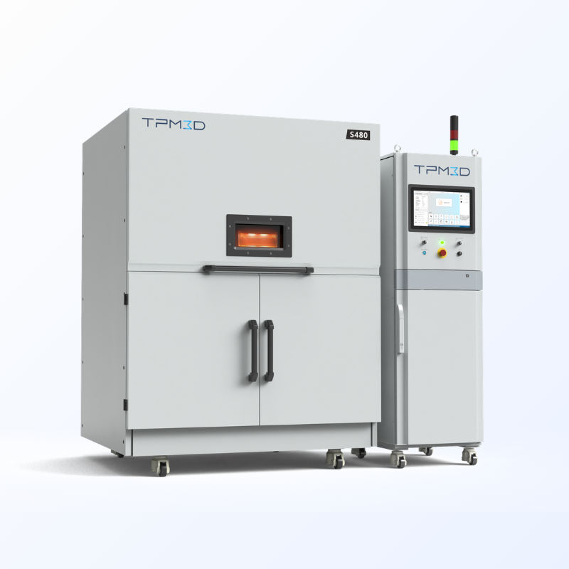
| S480 (High-Precision) | 480 × 480 × 600 mm | 100W CO₂ |
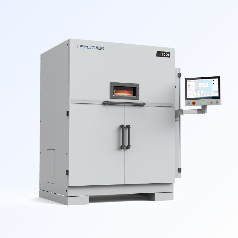
| P550DL (Large-Format Dual-Laser) | 550 × 550 × 850 mm | Dual 140W CO₂ |
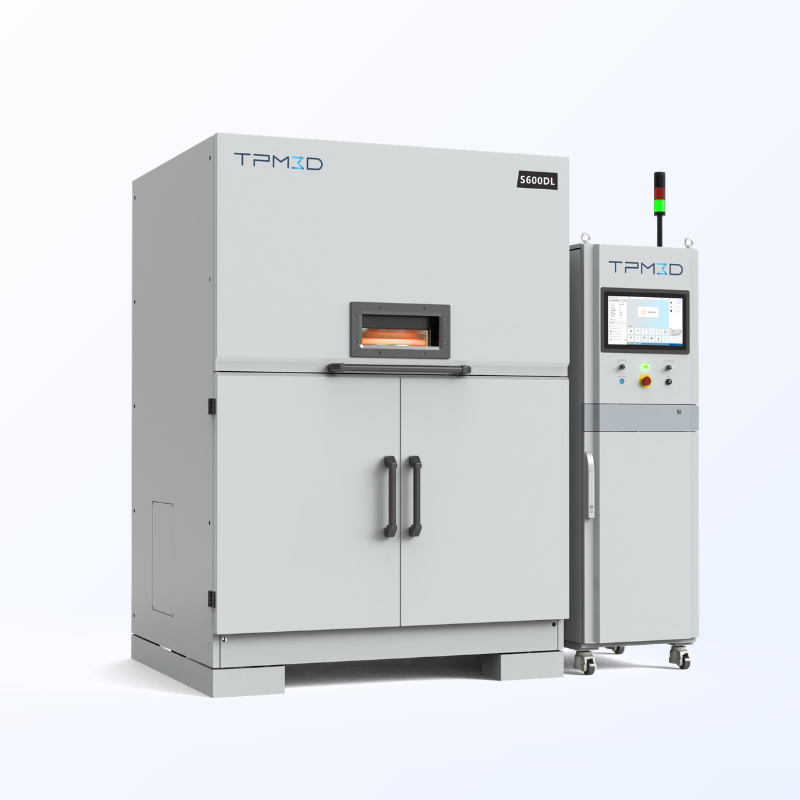
| S600DL (Large-Format Dual-Laser) | 600 × 600 × 800 mm | Dual 140W CO₂ |
This makes SLS an efficient choice when you need multiple design iterations or a small batch of test parts — design variants, tolerance studies, and fit checks can all run in the same build.
4. Isotropic Mechanical Properties
Unlike FDM (Fused Deposition Modelling), where Z-axis strength can be 50–70% of XY strength due to layer adhesion limits, SLS produces near-isotropic parts. The powder-bed fusion process creates consistent inter-layer bonding, with mechanical anisotropy typically under 5%.
Why this matters for prototypes: when you’re testing a load-bearing bracket or a snap-fit enclosure, you need the prototype to behave consistently regardless of how it was oriented during printing. SLS delivers this.
The SLS Rapid Prototyping Process
A typical SLS prototyping workflow on TPM3D systems, from design through finished part:
Pre-Print Preparation
1. Design for SLS
Design principles are recommended for application at the CAD stage.
- Minimum wall thickness: 0.4 mm
- Minimum hole diameter: 0.8 mm, subject to hole depth and whether it is a through-hole or blind hole
- Clearance for assembled parts: ≥0.5 mm when printing a mating assembly as a single piece; ≥0.2 mm for parts printed separately and assembled afterwards
- Internal cavities: design with powder removal in mind — include drain holes or access paths; enclosed hollow volumes trap unsintered powder and are difficult to clean
- Overhangs and unsupported spans: SLS does not require support structures, but large flat surfaces parallel to the build platform may experience slight warpage — consider ribbing or reorienting
2. Export STL and Import to Voxeldance
- Export STL (or native CAD format) from your design software
- Import into Voxeldance Additive for build preparation
3. Orient Parts and Auto-Nest
- For parts with specific surface quality or strength requirements: manually adjust orientation so that critical faces are positioned away from the build platform or aligned with the optimal axis
- For all other parts: use Voxeldance’s 3D auto-nesting to maximise powder bed utilisation
4. Slice and Export
- Set layer thickness — 0.12 mm is the standard recommendation for functional prototypes (thinner layers available for fine-detail parts, at the cost of longer print time)
- Configure remaining print parameters and run slicing
- Export the slice file
5. Laser Path Planning (BP)
- Import the slice file into Build Processor (BP) software to plan laser scanning strategies
- Export the final build file for the printer
Printing
6. Print
- Load the build file onto the printer and start the job
- The powder bed is preheated to just below the material’s melting point
- A CO₂ laser (or fibre laser on CF200) selectively scans each cross-section; the build platform lowers by one layer thickness, fresh powder is recoated, and the cycle repeats
- Typical build speed: 10–25 mm/hour (vertical), depending on part density and packing. S480 reaches scanning speeds up to 21,000 mm/s; P550DL uses dual 140W lasers for maximum throughput
7. Active Cooling
- After printing completes, active cooling runs for approximately 3 hours (full-height build)
- High-temperature materials such as PEEK require controlled cooling profiles to prevent warpage or crystallinity issues
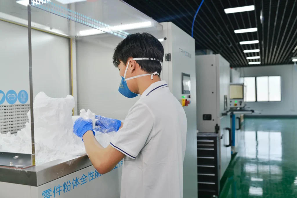
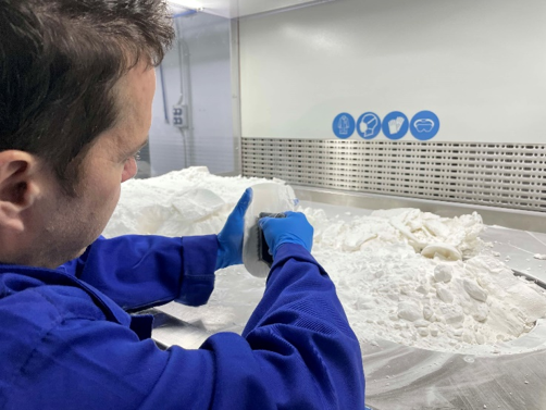
Post-Processing
8. Transfer to PPS — Natural Cooling and Powder Removal
- Move the build chamber to the PPS (Powder Processing Station)
- Allow parts to cool naturally within the powder cake
- Break out parts and remove loose powder — the PPS integrates cooling, breakout, powder sieving, and mixing into a single station
9. Sand Blasting and Powder Recycling
- Sand blast parts to remove residual surface powder and achieve a uniform matte finish
- Sieve, mix, and refresh unsintered powder through the PPS for reuse
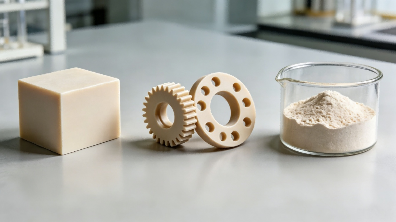
SLS Prototyping Materials at a Glance
The choice of material changes what you can test with the prototype. All values below are from TPM3D Precimid material datasheets:
| Material | Key Properties (TPM3D Datasheet) | Best For | Not Recommended For |
|---|---|---|---|
| PA12 (Precimid1172Pro) | Tensile 46 MPa (ASTM D638); elongation 8–17%; flexural modulus 1,280 MPa (ASTM D790); HDT 180 °C @0.45 MPa (ASTM D648) | General functional prototypes; enclosures; brackets; snap-fits; living hinges | High-temperature environments (>150 °C continuous) |
| PA11 | Higher elongation than PA12; better impact resistance; lower moisture absorption | Flexible components; ducting; parts subject to repeated impact | High-stiffness structural applications |
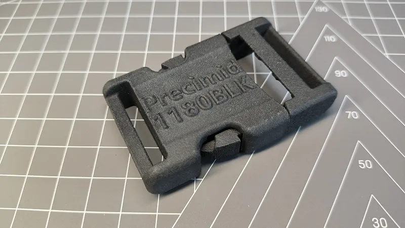
| PA12-GF30 (Precimid1176Pro GF30 BLK) | Tensile 41.7 MPa; flexural modulus 2,340 MPa (ISO 178); HDT 168 °C @0.45 MPa; 30% glass fibre fill | Rigid housings; jigs and fixtures; thermally stable components | Parts requiring high impact resistance |
| PA12-CF (Precimid1174Pro CF) | Tensile 88 MPa; flexural strength 135 MPa; tensile modulus 9,000 MPa; 30% carbon fibre fill | Drone frames; high-stiffness structural parts; lightweight aerospace components | Cost-sensitive applications |
| TPU (Precimid1130 88A) | Shore A 88–90; elongation 270%; excellent rebound and abrasion resistance | Seals; gaskets; protective covers; footwear components; flexible ducts | Load-bearing rigid parts |
| PP (TPM3D PP Pro) | Density 0.80 g/cm³; low water absorption; excellent chemical and fatigue resistance | Fluid containers; living hinges; chemical-resistant parts | High-temperature or high-stiffness applications |
| PEEK (TPM3D PEEK IND) | Tensile 80 MPa (ASTM D638); HDT 294 °C @0.45 MPa (ASTM D648); flexural modulus 4,000 MPa (ASTM D790); density 1.13 g/cm³ | Aerospace engine components; high-temp functional prototypes; structural parts | Cost-sensitive applications (material price premium) |
All values are from TPM3D Precimid material datasheets based on ASTM/ISO standardised testing. Actual values may vary with processing parameters and part geometry. Always validate with your own testing for critical applications.
SLS vs Traditional Prototyping Methods
| Criterion | SLS (Nylon) | CNC Machining | Injection Moulding (Soft Tool) | FDM |
|---|---|---|---|---|
| Lead time (5 parts) | 2–4 days | 5–10 days | 2–4 weeks | 1–3 days |
| Part cost (small batch) | Moderate | High (labour + setup per part) | High up-front + low unit cost | Low–moderate |
| Geometry freedom | Near-unlimited (internal channels, lattices, undercuts) | Limited by tool access | Limited by draft angles and ejection | Moderate (supports required for overhangs) |
| Mechanical isotropy | Near-isotropic (<5% variation) | Isotropic by nature | Isotropic | Anisotropic (Z-axis 50–70% of XY) |
| Surface finish (as-built) | Matte, slightly grainy (Ra 8–12 μm) | Machined (Ra 1–3 μm) | Mould-finish dependent | Visible layer lines (Ra 10–25 μm) |
| Material options | PA12, PA11, PA12-GF, PA12-CF, TPU, PP, PEEK | Metals, engineering plastics | Most thermoplastics | ABS, PLA, PETG, PC, ULTEM |
| Scalability | Medium — single build = dozens of parts | Low — one part at a time per spindle | High — thousands of parts per mould | Low — one part at a time per extruder |
When SLS is the Right Choice:
- You need functional prototypes in engineering-grade nylon
- Your design has complex internal geometry or undercuts
- You want to test mechanical behaviour (strength, snap-fit, fatigue) not just visual appearance
- You need prototypes in the same material as eventual production parts
- You are iterating rapidly and need next-day turnaround — as demonstrated by GAC R&D Centre’s 4-day cycle (see case study below)
When Another Method May Be Better:
- Go CNC if you need tight tolerances (±0.05 mm or better), metal prototypes, or a specific engineering plastic not available in powder form
- Go FDM if you need a single visual model, lowest cost, or wide material availability (PEEK in filament form, for example)
- Go soft tooling if you’re confident in the design and need 100+ parts for field testing
Real-World SLS Prototyping Applications
The following case studies are based on published TPM3D customer deployments and publicly reported results.
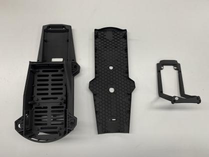
Aerospace & UAV: 6-Gram Drone Frame
When every gram matters, SLS carbon-fibre nylon enables topology-optimised structures impossible to machine.
A micro-UAV frame measuring just 66 × 66 × 32.6 mm was printed in a single piece on a TPM3D SLS system using Precimid1174Pro CF (30% carbon-fibre-reinforced PA12). The result: a frame weighing 6 grams (full aircraft: 35 g), with tensile strength reaching 88 MPa — a 91% improvement over pure PA12. The same material system passed four operational validation tests: static load, thermal cycling (−20 to +60 °C), electromagnetic shielding, and 8 m/s high-manoeuvrability flight.
Source: TPM3D case study, June 2025.
Automotive: GAC R&D Centre — From 2–3 Weeks to 4 Days
GAC R&D Centre’s prototype engineering department previously relied on a six-step outsourced workflow for interior/exterior trim, thermal management, and powertrain component prototypes. By bringing SLS in-house with a TPM3D P550DL system and Precimid1172Pro PA12 powder, they:
- Reduced the workflow from 6 steps to 4 steps
- Cut lead time from 2–3 weeks to as fast as 4 days (over 70% reduction)
- Gained full control over confidential design data
- Validated parts across four categories: appearance, structure, assembly fit, and ergonomics
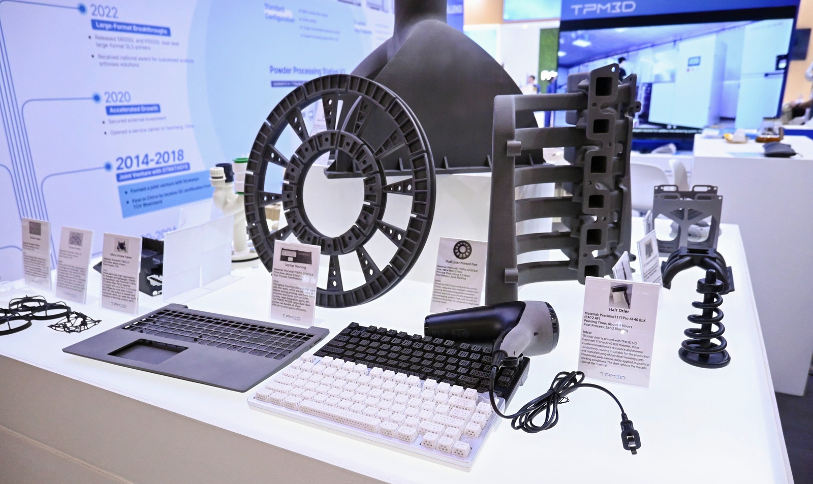
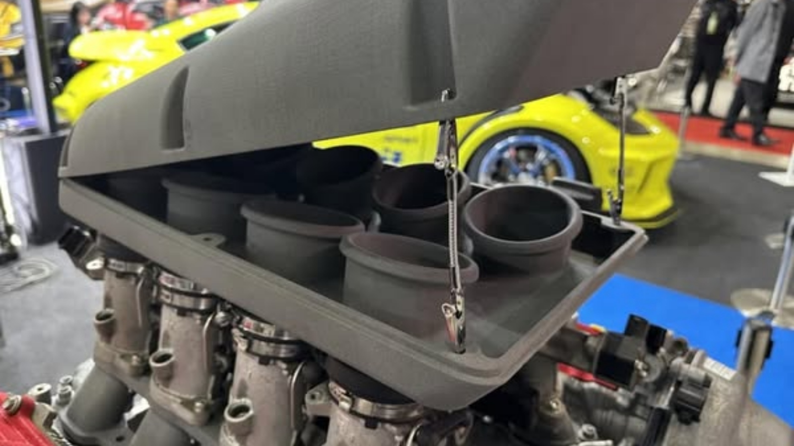
Additional automotive deployments include Dongfeng Motor’s trial-production department using a TPM3D S480 with PA12-GF30 for centre console panels and electrical distribution housings, and DTM Racing Sport’s 1.9 kg V8 intake manifold — exploiting SLS’s ability to produce complex internal geometries in a single print.
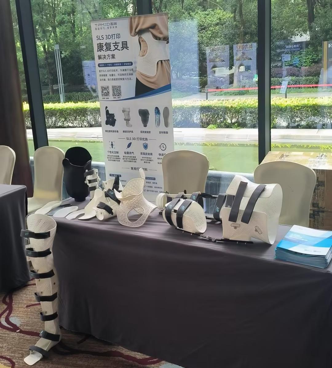
Medical: AK Medical — Surgical Guides from 30% Error to <5%
AK Medical deployed a TPM3D P360 SLS system with PPS post-processing station and biocompatible PA12 to produce patient-specific orthopaedic surgical guides. In joint replacement procedures, the SLS-printed guides achieve sub-millimetre bone fit, reducing lower-limb alignment deviation exceeding 3° from approximately 30% to below 5%. Intraoperative blood loss and 24-hour drainage were also significantly reduced (P<0.01).
The system operates under CE certification and dust-explosion-proof (Zone 22) compliance, with integrated nitrogen generation for medical-grade clean production.
Medical: Edser Labs — Digital Orthotic Insoles at Scale
Edser Labs (Spain), a clinical orthotics manufacturer with nearly 30 years of experience, adopted a TPM3D S600DL dual-laser system with PP Pro powder to produce custom orthotic insoles. The digital workflow — foot scan via LiDAR → CAD design → SLS printing — reduced single-layer print time by nearly 50% through dual-laser scanning.
The PP Pro material supports near-100% powder recycling through an optimised sieving and refresh system. Edser projects that 90% of its products will eventually be made via additive manufacturing.
In-House SLS vs Outsourcing
If your prototyping demand is sporadic (1–3 projects/month), outsourcing to an SLS service bureau is often more cost-effective — no capital expenditure, no powder management, no maintenance.
If your demand is consistent (10+ prototype builds/month), in-house SLS becomes economically attractive. Key considerations:
| Factor | Outsourcing (Service Bureau) | In-House SLS |
|---|---|---|
| Up-front investment | $0 | Equipment investment — TPM3D industrial systems start from compact formats |
| Lead time | 3–7 business days (incl. shipping) | 1–3 business days |
| Per-part cost | Service markup | Material + machine time only |
| Design confidentiality | Files leave your organisation | Fully internal |
| Iteration speed | Limited by bureau turnaround | Unlimited — print overnight |
| Material options | Depends on bureau’s capabilities | You control material selection |
For organisations considering in-house SLS, TPM3D’s product line spans from the CF200 compact professional system (200 × 200 × 320 mm, 30W fibre laser, <1 m² footprint, 220V plug-and-play) through mid-range industrial systems (S360/P360 at 360 × 360 × 600 mm) to large-format dual-laser production systems (P550DL at 550 × 550 × 850 mm and S600DL at 600 × 600 × 800 mm).
All systems support the core prototyping materials — PA12, PA11, PA12-GF, PA12-CF, TPU, and PP — with the S320HT extending capability to PEEK, PEKK, and PPS at build temperatures up to 350 °C.
Getting Started with SLS Prototyping: A Practical Checklist
Step 1 — Define your prototyping requirements
- What materials do you need? (PA12 for general-purpose, PA11 for ductility, TPU for flexible parts, PEEK for high-temp?)
- What’s the largest single part dimension?
- Typical batch size per iteration?
- Required turnaround time?
Step 2 — Choose your approach
- In-house or outsourced? (Use the table above as a decision guide)
- If in-house: evaluate equipment options based on build volume, material range, and throughput
- If outsourcing: request sample parts in your target material from 2–3 providers
Step 3 — Prepare your first build
- Apply design principles at the CAD stage: wall thickness ≥0.4 mm, hole diameter ≥0.8 mm, clearance ≥0.5 mm (one-piece assembly) / ≥0.2 mm (separate assembly)
- Export STL at appropriate resolution (chordal tolerance ≤0.05 mm)
- Import into Voxeldance Additive, orient critical surfaces for optimal finish/strength, auto-nest remaining parts
- Slice at 0.12 mm layer thickness, process through BP, and load onto printer
Step 4 — Validate and iterate
- Inspect first-article parts for dimensional accuracy
- Conduct functional testing in the intended environment
- Document process parameters for reproducibility
- Iterate design based on test results — the same build can include multiple variants side-by-side
Frequently Asked Questions
Q: How accurate are SLS prototypes?
A: Typical dimensional accuracy is ±0.2 mm for well-designed parts on calibrated industrial equipment. Tight-tolerance features (<0.2 mm) may require post-machining or design compensation. TPM3D’s S480 achieves scanning speeds of 21,000 mm/s with 0.31 mm laser spot size for high-precision applications.
Q: Can SLS prototypes be post-machined? A: Yes. PA12 and PA11 SLS parts can be drilled, tapped, reamed, and CNC-finished. This is common when specific mating surfaces require tighter tolerances than SLS alone can achieve.
Q: How does SLS part cost compare to CNC for low-volume projects?
A: SLS becomes cost-competitive when geometry is complex (undercuts, internal channels) or when multiple parts can be nested in a single build. For simple prismatic parts, CNC is usually cheaper. The break-even depends on geometry, not just quantity. GAC R&D Centre’s transition from outsourced workflow to in-house SLS delivered a >70% lead-time reduction.
Q: Can SLS produce clear or transparent parts? A: No. SLS PA12 parts are opaque white/off-white in their natural state. They can be dyed black or other dark colours, but cannot be made transparent. For transparent prototypes, consider SLA or PolyJet.