If you are designing functional plastic parts — brackets, housings, snap-fits, ducting, wearable devices — and you need them to work, not just look right, plastic powder bed fusion (PBF) is probably on your shortlist. It is the only mainstream 3D printing process that produces dense, isotropic parts in engineering-grade thermoplastics with zero support structures.
This guide covers what plastic PBF is, how it works, what materials it can process, what to look for in a machine, and what real deployments look like — all backed by certified material datasheets and published case data from TPM3D customers.
What Is Plastic Powder Bed Fusion?
Powder bed fusion is one of the seven categories of additive manufacturing defined by ISO/ASTM 52900. In the plastic (polymer) variant, a laser selectively fuses thermoplastic powder layer by layer inside a heated chamber. The most widely used implementation is Selective Laser Sintering (SLS), where a CO₂ or fibre laser scans each cross-section of the part.
The key thing to understand: the powder bed is preheated to just below the material’s melting point. The laser only needs to provide the last bit of energy to fuse each layer. This is fundamentally different from metal PBF (SLM/DMLS), where the laser does all the melting work from room temperature — and it is why plastic PBF does not need support structures. The unsintered powder surrounding the part holds everything in place.
SLS vs Other PBF Variants
The term “powder bed fusion” covers several process variants. Here is how they relate:
| Process | Heat Source | Material | Supports Needed? | What It Makes |
|---|---|---|---|---|
| SLS (Selective Laser Sintering) | CO₂ or fibre laser | Polymer powder (PA12, PA11, TPU, PP, PEEK) | No — powder is self-supporting | Functional plastic parts |
| SLM (Selective Laser Melting) | Fibre laser (200–1000W) | Metal powder | Yes — extensive anchors | Dense metal parts |
| DMLS (Direct Metal Laser Sintering) | Fibre laser | Metal powder | Yes | Metal parts (sintering mechanism) |
| EBM (Electron Beam Melting) | Electron beam (vacuum) | Metal powder | Minimal — powder pre-sintered | Aerospace and implant-grade metal |
| SHS (Selective Heat Sintering) | Thermal print head | Thermoplastic powder | No | Concept models only (low strength) |
This guide focuses on laser-based plastic PBF — the SLS process. That is the technology behind every TPM3D system, and the one most engineers mean when they say “plastic powder bed fusion.”
Why No Support Structures Changes Everything
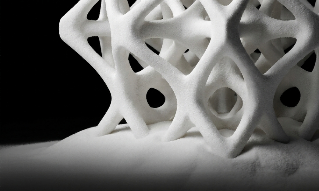
In FDM, SLA, and metal PBF, you design around support structures — where will they go, how will you remove them, what surfaces will they mark. In plastic PBF, the unsintered powder is the support. You can print:
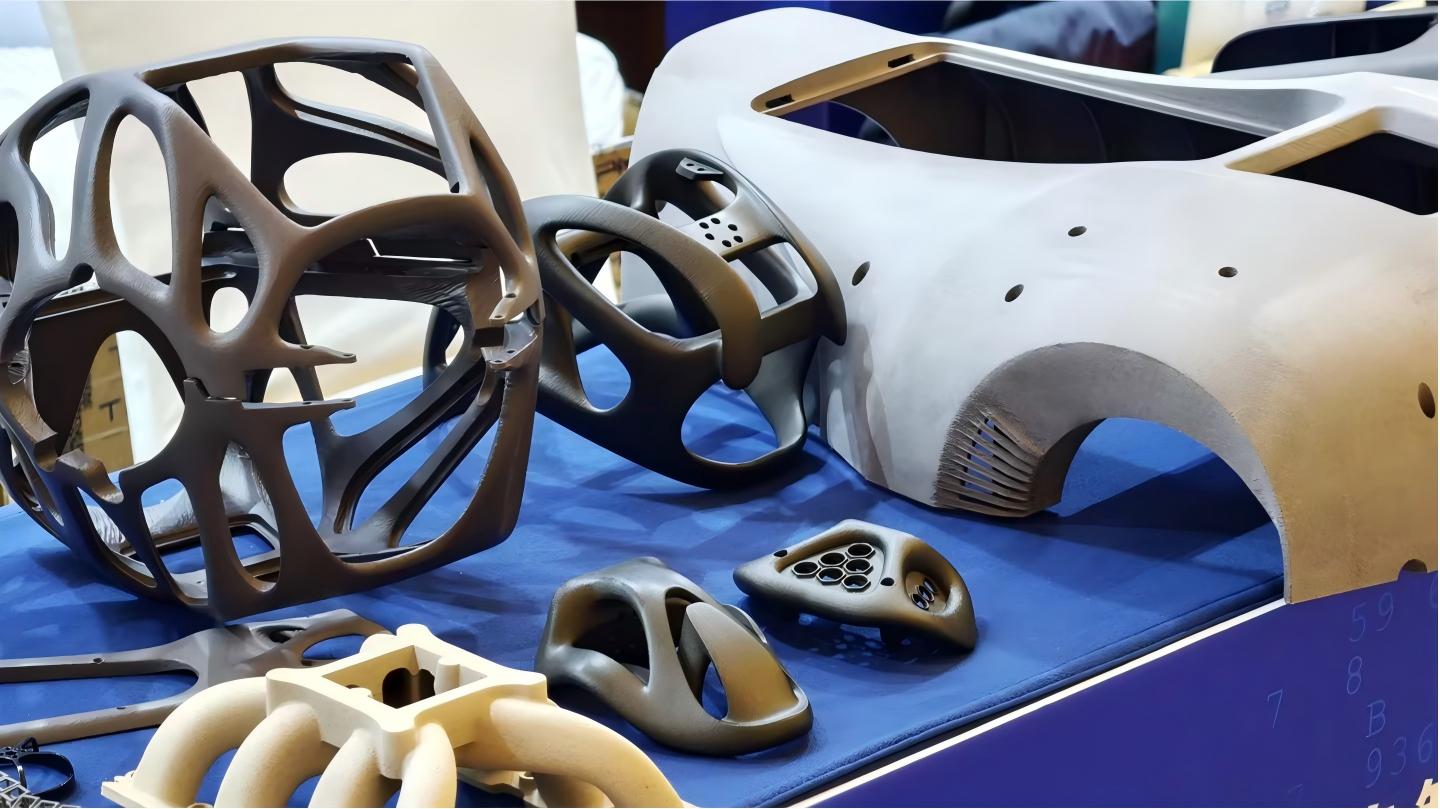
- Internal channels and conduits without access holes for support removal
- Snap-fit assemblies and living hinges in one piece
- Lattice structures and lightweighting geometries
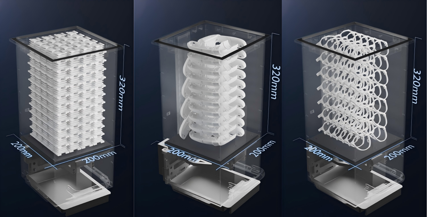
- Nested or stacked parts for batch production
The trade-off: surface finish is matte and slightly grainy (Ra 8–12 μm), not the glass-smooth surface of SLA. For functional parts, this is usually a non-issue. For cosmetic surfaces, a quick bead blast or vapour smooth is all it takes.
How Plastic Powder Bed Fusion Works
The process is straightforward in concept and consists of four stages:
1. Prepare. Design your part in CAD following SLS design rules — minimum wall 0.4 mm, minimum hole 0.8 mm, clearance ≥0.5 mm for one-piece assemblies. Export as STL, import into Voxeldance Additive (TPM3D Version) for orientation and 3D auto-nesting, slice at 0.12 mm layer thickness, and plan the laser path in Build Processor (BP) software.
2. Print. The powder bed is preheated to just below melting (around 170 °C for PA12). A laser scans each cross-section, fusing the powder into a solid layer. The build platform drops by one layer thickness, a recoater blade spreads fresh powder, and the cycle repeats. Typical vertical build speed is 10–25 mm/hour depending on part density and nesting.
3. Cool. After printing, the build chamber cools actively for about 3 hours (full-height build). High-temperature materials like PEEK need controlled cooling profiles to prevent warpage. The build cake — sintered parts encased in unsintered powder — then transfers to the PPS (Powder Performance Station) for natural cooling and breakout.
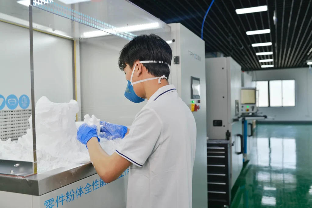
4. Post-process. Parts come out of the powder cake, get bead-blasted to remove residual surface powder, and are inspected. Unsintered powder is sieved, mixed with fresh powder, and returned to the supply — TPM3D’s PA12 supports up to 80% recycling, and optimised workflows can push that near 100%.
For a deep dive into design rules, the full 9-step workflow, and cost modelling, see our SLS Rapid Prototyping Complete Guide.

Plastic PBF Materials — What Can You Actually Print?
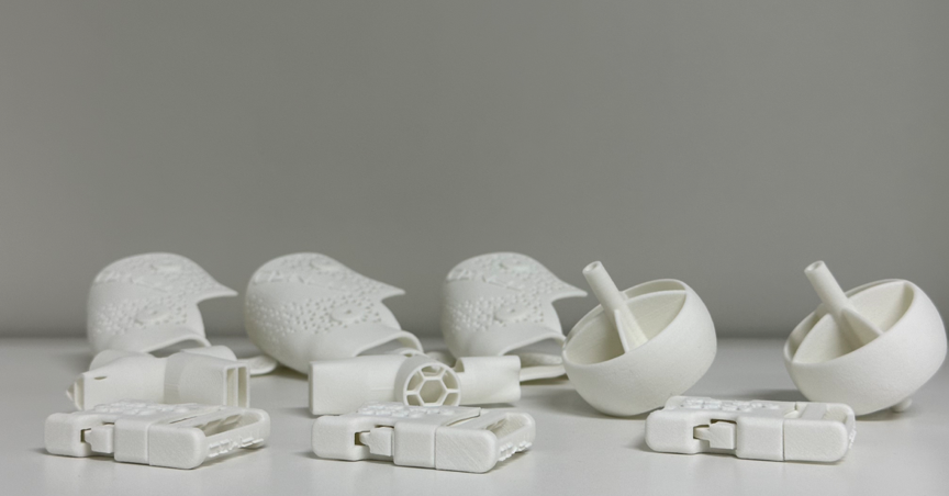
Material choice determines what your parts can do. The advantage of plastic PBF over other 3D printing processes is that you print in the same engineering thermoplastics used in injection moulding — not “prototype materials” that behave differently from production parts.
Here is the TPM3D material portfolio, all tested to ASTM or ISO standards:
| Material | Tensile Strength | Elongation | Flexural Modulus | HDT (0.45 MPa) | Best For |
|---|---|---|---|---|---|
| PA12 (Precimid1172Pro) | 46 MPa (ASTM D638) | 8–17% | 1,280 MPa (ASTM D790) | 180 °C | General functional parts — enclosures, brackets, snap-fits, living hinges. Covers ~80% of PBF applications. |
| PA11 | Higher than PA12 | Higher than PA12 | Lower than PA12 | Moderate | Flexible components, ducting, repeated-impact parts. Better ductility and lower moisture absorption. |
| PA12-GF30 (Precimid1176Pro GF30) | 41.7 MPa | Lower | 2,340 MPa (ISO 178) | 168 °C | Rigid housings, jigs, fixtures, thermally stable parts. 30% glass fibre for +83% stiffness vs. unfilled PA12. |
| PA12-CF (Precimid1174Pro CF) | 88 MPa | Lower | 9,000 MPa | Moderate | Drone frames, high-stiffness structural parts. 30% carbon fibre — +91% tensile strength vs. unfilled PA12. |
| TPU (Precimid1130 88A) | 8 MPa | 270% | 70 MPa | — | Seals, gaskets, protective covers, footwear, flexible ducts. Shore A 88–90, excellent rebound and abrasion resistance. |
| PP (TPM3D PP Pro) | 21.1 MPa | 18.0% | 1,100 MPa | 98 ℃ | Fluid containers, living hinges, chemical-resistant parts. Density 0.80 g/cm³ — the lightest option. Near-100% recyclable. |
| PEEK (TPM3D PEEK IND) | 80 MPa (ASTM D638) | 6.3% | 4,000 MPa (ASTM D790) | 294 °C | Aerospace components, high-temp functional prototypes, structural parts. Requires the S320HT high-temperature system. |
All values from TPM3D Precimid® material datasheets based on ASTM/ISO standardised testing. Actual values may vary with processing parameters and part geometry.
How to Choose — Quick Decision Guide
- Just getting started? PA12 covers most use cases. It is the workhorse material of SLS.
- Need more stiffness without changing material class? PA12-GF30 (glass-filled) gives you nearly double the flexural modulus.
- Need maximum strength-to-weight? PA12-CF (carbon-filled) nearly doubles tensile strength at the same weight.
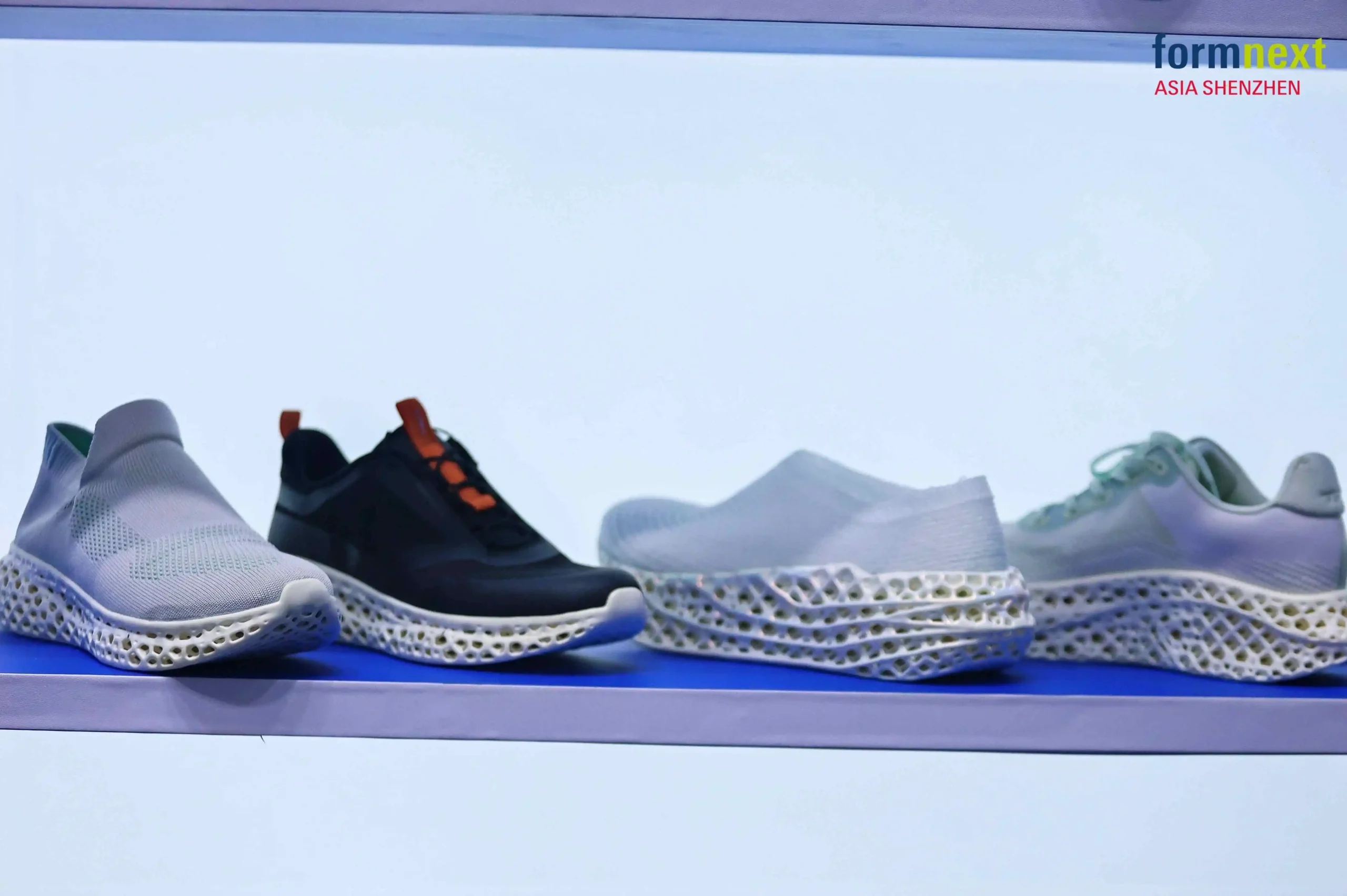
- Need flexibility? TPU at Shore A 88 is your elastomer — think shoe soles, seals, bellows.
- Need chemical resistance or ultra-low weight? PP at 0.80 g/cm³ is lighter than water and handles aggressive chemicals.
- Need to go above 250 °C? PEEK is the answer — but you will need the S320HT system (build chamber up to 350 °C).
PEEK 3D Printing: Complete Guide to High-Temperature Additive Manufacturing
TPM3D Plastic PBF Machine Lineup
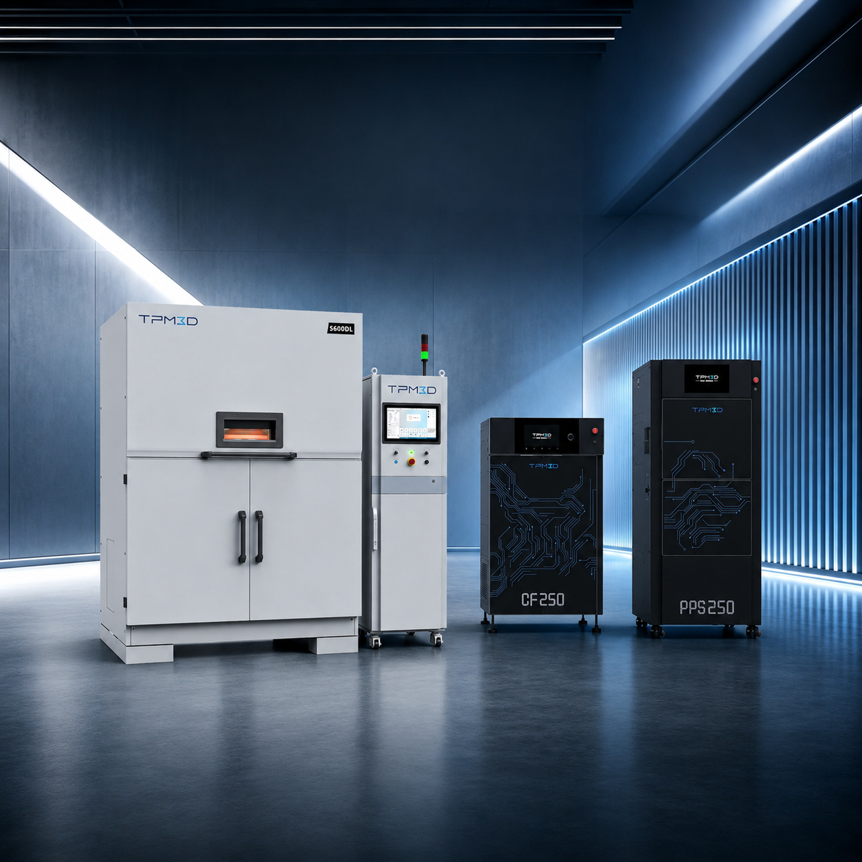
Seven industrial systems across the S‑Series and P‑Series, from compact desktop to large-format dual-laser production platforms. All share the same material ecosystem, software chain (Voxeldance Additive + Build Processor), and PPS post-processing integration.
| Model | Build Volume (X×Y×Z) | Laser | Material Range | What It Is Built For |
|---|---|---|---|---|
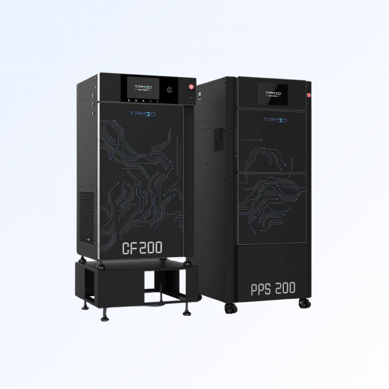
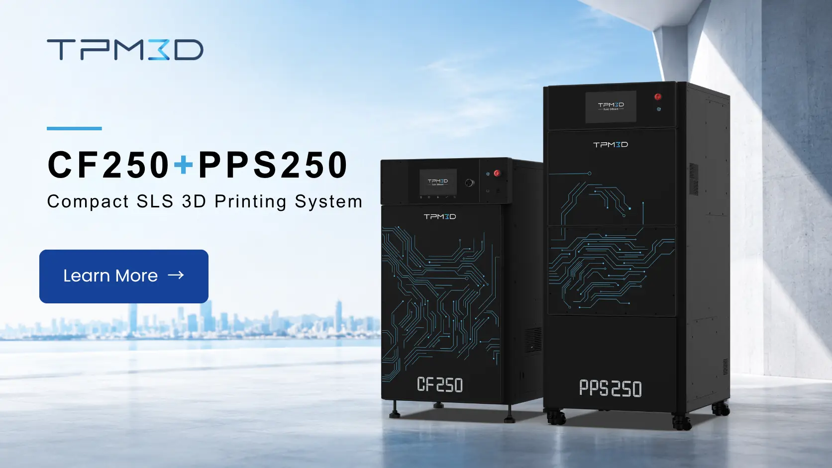
| CF200 | 200 × 200 × 320 mm | 30W fibre | PA12, PA11, TPU | Compact professional. Under 1 m² footprint, 220V plug-and-play. |
| S260 | 260 × 260 × 450 mm | 30W CO₂ | PA12, PA11, TPU, PP | Education and research. Affordable entry into full-size SLS. |
| S320HT | 320 × 320 × 380 mm (large) / 250 × 250 × 380 mm (small) | 60W CO₂ | PEEK, PEKK, PPS | High-temperature specialist. Build chamber up to 350 °C. The only system in the lineup that runs PEEK. |
| S360 / P360 | 360 × 360 × 600 mm | 60W CO₂ | PA12, PA11, TPU, PP, PA12-GF, PA12-CF | The versatile workhorse. Best balance of build volume and cost for most industrial users. |
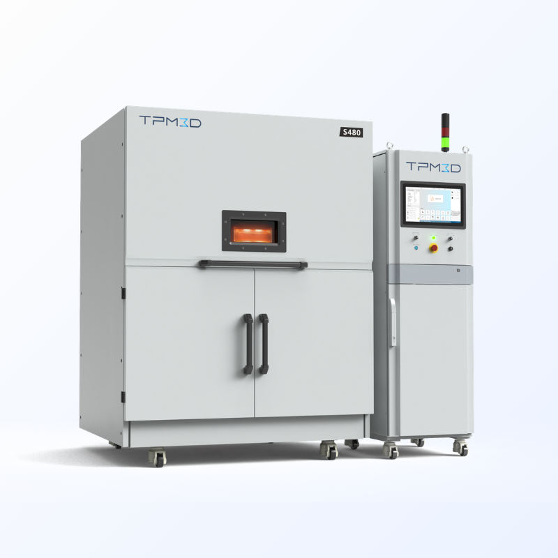
| S480 | 480 × 480 × 600 mm | 100W CO₂ | PA12, PA11, TPU, PP, PA12-GF, PA12-CF | High-precision production. 0.31 mm spot, 21,000 mm/s scan speed. |
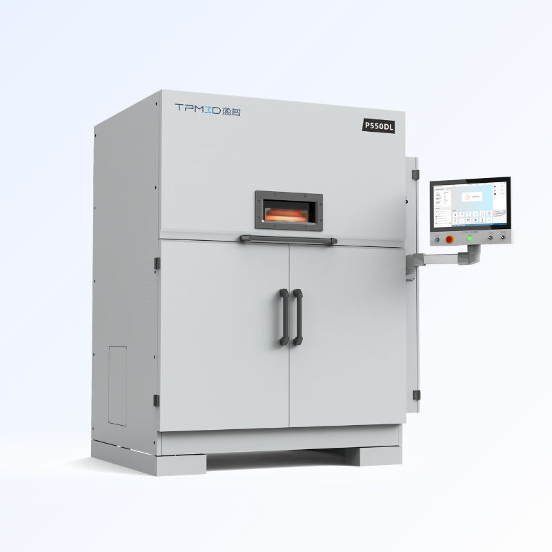
| P550DL | 550 × 550 × 850 mm | Dual 140W CO₂ | PA12, PA11, TPU, PP, PA12-GF, PA12-CF | Large-format dual-laser. Maximum throughput for serial production. |
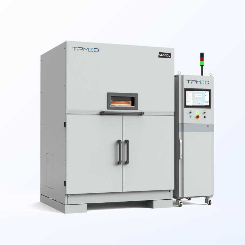
| S600DL | 600 × 600 × 800 mm | Dual CO₂ | PA12, PA11, TPU, PP, PA12-GF, PA12-CF | Largest build volume in the lineup. Dual-laser for maximum part count per build. |
The S‑Series covers five models optimised for precision and material versatility — from the entry-level S260 and high-temperature S320HT to the dual-laser S600DL. The P‑Series delivers two high-throughput platforms (P360 and P550DL) with integrated nitrogen generation, top-loaded powder feeding, and compact footprints designed for continuous production.
Compare full specifications and see all models side by side:
What to Look for When Choosing a Plastic PBF Printer
Build Volume — Think About Nesting, Not Just Part Size
Build volume determines the largest single part you can produce — but more importantly, it determines how many parts you can nest per build. A system that fits your largest part today may only hold 5 parts per build, while a slightly larger one holds 20. Since laser scan time is the main cost driver, more parts per build means lower cost per part.
- Compact (≤260 mm): Education, small prototypes, single-component runs
- Mid-range (300–360 mm): Most industrial applications — housings, brackets, assemblies
- Large-format (≥480 mm): Automotive interior panels, large ducting, multi-part production builds
Laser Power and Type
| Laser | Power | What It Means |
|---|---|---|
| Fibre laser | 30W | Finer spot size, ideal for compact systems and detailed parts |
| Single CO₂ | 30–100W | Standard for industrial SLS. Higher wattage = faster scanning, deeper fusion |
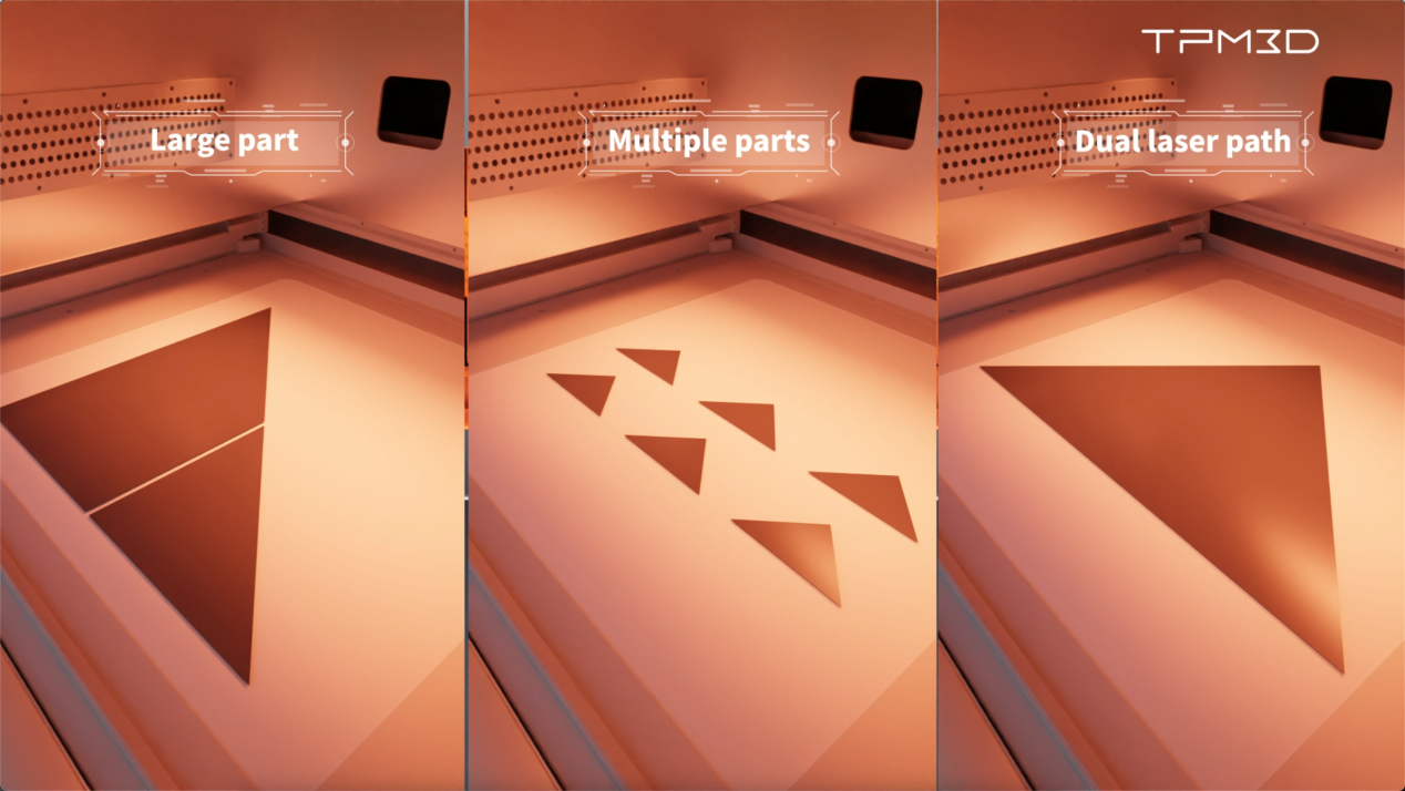
| Dual CO₂ | 2 × 140W | Two lasers scan simultaneously — roughly halves print time for large builds |
If you are running production builds every day, dual-laser systems deliver significantly lower cost per part. If you are doing R&D or low-volume prototyping, a single laser is perfectly adequate.
Powder Recycling — The Hidden Cost Variable
Powder is the largest consumable cost in plastic PBF. A system with integrated sieving, mixing, and fresh powder dispensing can dramatically reduce waste:
- TPM3D PPS integrates cooling, breakout, sieving, and mixing in one station
- PA12 supports up to 80% powder reuse (Precimid1172Pro)
- Optimised workflows — like Edser Labs running PP Pro — achieve near-100% recycling
The difference between 50% and 80% recycling rate is not marginal. Over a year of production, it can mean thousands of dollars in material savings.
Software — The Part You Touch Every Day
The software chain determines how fast you can go from CAD to printed part. Look for:
- Voxeldance Additive (TPM3D Version): STL import, manual orientation, 3D auto-nesting, slicing
- Build Processor: Laser scan strategy, fill patterns, parameter control
- Open file formats for compatibility with your existing design tools
Certification and Compliance
For industrial and medical applications, third-party certification is not optional:
- CE certification (TÜV Rheinland): Electrical safety and electromagnetic compatibility
- ATEX Zone 22 compliance: Required for polymer powder processing environments (dust explosion prevention)
- ISO 9001: Quality management system
- Material biocompatibility: USP Class VI or ISO 10993 for medical-grade PA12
TPM3D systems are TÜV Rheinland CE certified and ATEX Zone 22 compliant, with deployments in medical, automotive, and aerospace environments across Europe, Asia, North America, and the Middle East.
What People Are Making With It — Real Deployments
Automotive: GAC R&D Centre Cut Prototyping Lead Time by 70%
GAC R&D Centre’s prototype engineering department used to outsource every prototype through a six-step vendor process — design, export, quote, wait, ship, receive. Lead times ran 2–3 weeks per iteration.
After bringing a TPM3D P550DL and Precimid1172Pro PA12 in-house, the workflow dropped to four steps and lead time fell to as fast as 4 days — a 70%+ reduction. The team now handles four validation categories in-house: appearance, structure, assembly fit, and ergonomics, with full control over confidential design data.
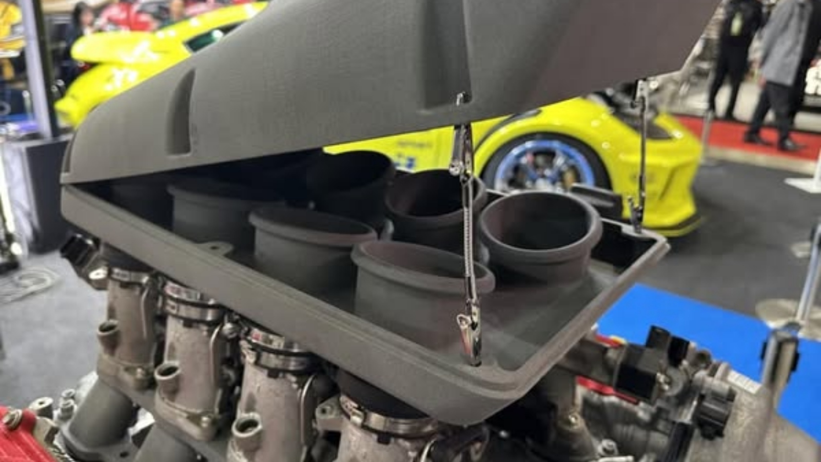
Other automotive deployments: Dongfeng Motor uses a TPM3D S480 (part of the S Series) with PA12-GF30 for centre console panels; DTM Racing Sport produced a 1.9 kg V8 intake manifold that exploited SLS’s ability to print complex internal geometries impossible with injection moulding.
Medical: Surgical Guide Alignment Error Dropped from 30% to Under 5%
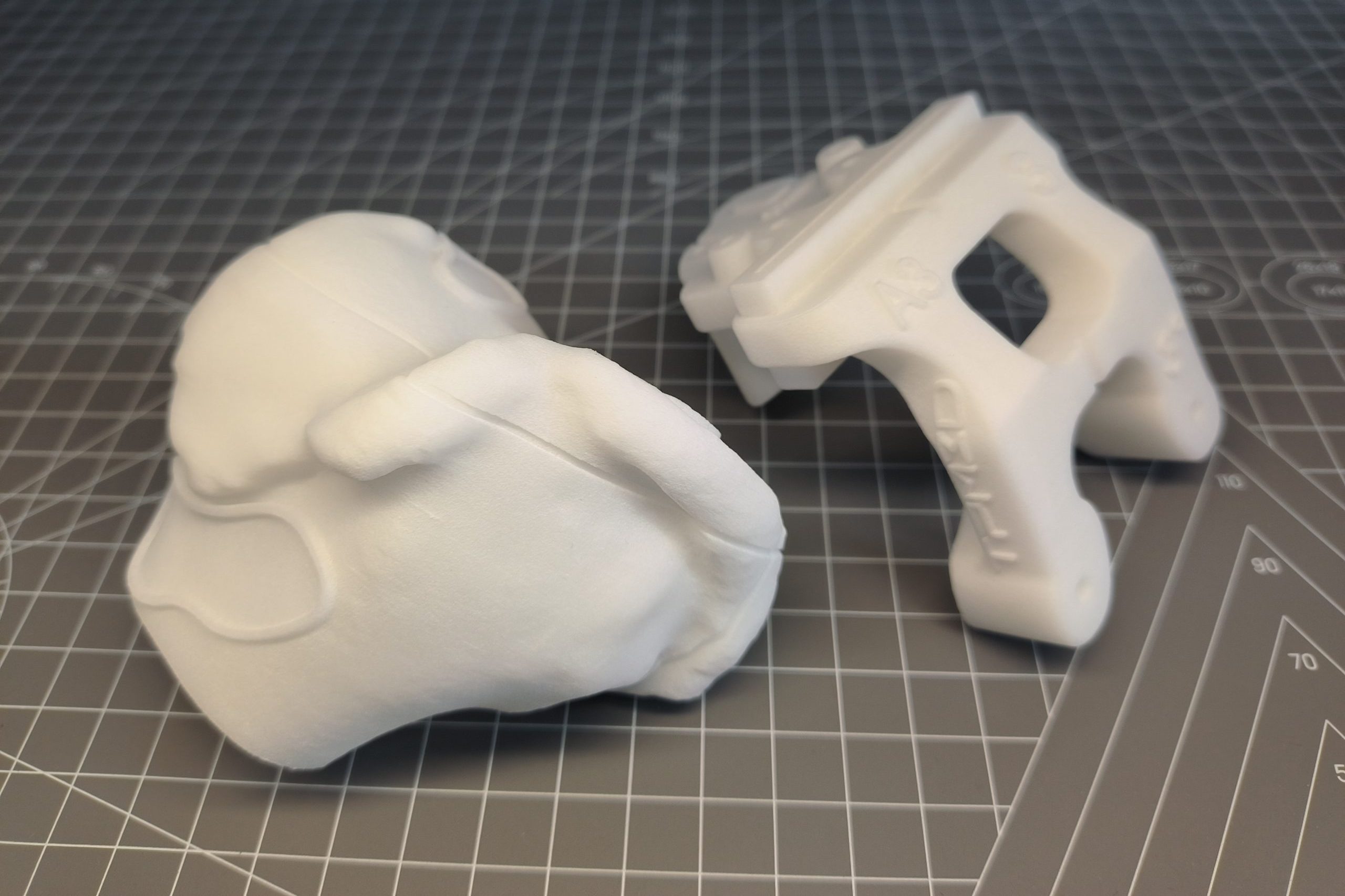
AK Medical deployed a TPM3D P360 (part of the P Series) with biocompatible PA12 to produce patient-specific orthopaedic surgical guides. SLS-printed guides achieve sub-millimetre bone surface fit, which reduced lower-limb alignment deviation exceeding 3° from approximately 30% of cases to below 5%.
The system operates under CE certification and Zone 22 dust-explosion compliance with integrated nitrogen generation. Since 2025, China’s NHSA has included medical 3D printing guide templates in its billing catalogue — accelerating adoption from a premium option to standard practice.
Aerospace and UAV: A 6-Gram Drone Frame at 88 MPa
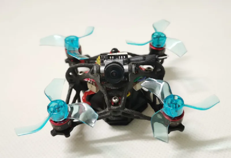
A micro-UAV frame (66 × 66 × 32.6 mm) was printed in Precimid1174Pro CF (30% carbon-fibre PA12) on a TPM3D SLS system. The frame weighs 6 grams (full aircraft 35 g) with a tensile strength of 88 MPa — 91% higher than unfilled PA12. It passed static load testing, thermal cycling (−20 to +60 °C), electromagnetic shielding checks, and 8 m/s high-manoeuvrability flight tests.
This is where carbon-filled PA12 and zero-support SLS combine: complex internal reinforcement channels, thin-wall structures, and lightweighting lattices — all in a single print, at strengths approaching aluminium.
Consumer Products: Edser Labs Scaling to 90% Additive
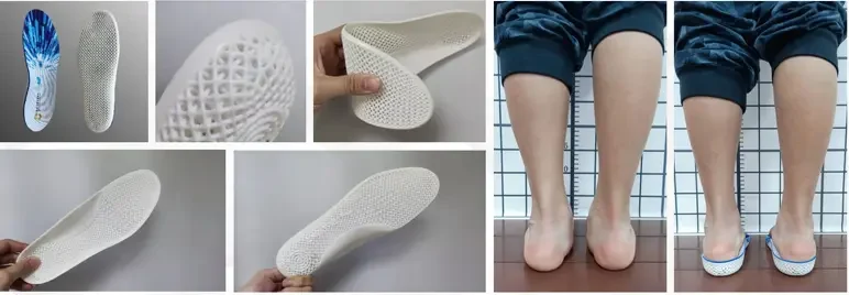
Edser Labs (Spain) uses a TPM3D S600DL (part of the S Series) dual-laser system with PP Pro powder for custom orthotic insoles. The digital workflow — LiDAR foot scan → CAD → SLS print — cuts single-layer print time approximately 50% via dual-laser scanning. PP Pro powder recycling approaches 100%, meaning almost no material waste.
Edser projects that 90% of its products will be additively manufactured — a shift from traditional orthotic fabrication that would have been economically impossible without near-zero-waste SLS.
3D Printing Prosthetics: Benefits, Materials, Applications & Real-World Examples
Plastic PBF vs Other 3D Printing Technologies
| Criterion | Plastic PBF (SLS) | FDM | SLA | Metal PBF (SLM) |
|---|---|---|---|---|
| Material | Engineering thermoplastics (PA12, TPU, PEEK) | Filament (PLA, ABS, PETG) | Photopolymer resin | Metal powder (Ti, Al, steel) |
| Supports | None — powder self-supports | Required for overhangs | Required | Required (extensive) |
| Isotropy | Near-isotropic (<5% variation) | Anisotropic (Z is 50–70% of XY) | Isotropic but brittle | Near-isotropic |
| Surface (as-built) | Matte, grainy (Ra 8–12 μm) | Visible layer lines (Ra 10–25 μm) | Smooth (Ra 1–5 μm) | Rough (Ra 10–20 μm) |
| Functional durability | High — real engineering plastics | Moderate | Low — UV degradation over time | Very high |
| Best for | Functional prototypes, low-volume production | Concept models, cheap prototypes | Visual prototypes, jewellery, dental | Metal end-use parts, tooling |
The short version: if you need parts that function like injection-moulded nylon, PBF is your process. If you just need to check a shape, FDM is cheaper. If you need cosmetics, SLA is smoother. If you need metal, that is a different conversation entirely.
Read more:
SLS vs. FDM vs. SLA vs. MJF: When to Choose Each for End‑Use Production (2026)
FDM vs SLS 3D Printing: Which Technology Is Best for Functional Parts and Production?
3D Printing vs Injection Molding: Which Saves More Time & Cost in 2026?
SLA vs. SLS: The Engineer’s Guide to Choosing the Right Laser-Based 3D Printing Technology
Frequently Asked Questions
Is plastic powder bed fusion the same as SLS?
Yes. SLS (Selective Laser Sintering) is the most common industrial implementation of plastic powder bed fusion. The terms “polymer PBF,” “plastic LPBF,” and “SLS” are used interchangeably in the industry, though SLS is the original and most widely recognised term. All TPM3D systems use the SLS process.
What materials can a plastic PBF printer process?
PA12 (nylon 12) and PA11 (nylon 11) cover the majority of applications. Filled variants — PA12-GF30 (glass fibre) and PA12-CF (carbon fibre) — add stiffness and strength. TPU produces flexible elastomeric parts. PP offers chemical resistance and ultra-low density. High-performance polymers like PEEK, PEKK, and PPS require specialised high-temperature systems (the TPM3D S320HT, for example).
What is the typical accuracy of plastic PBF parts?
Dimensional accuracy of ±0.2% (minimum ±0.2 mm) is typical on calibrated industrial equipment. The TPM3D S480 achieves a 0.31 mm laser spot with 21,000 mm/s scanning speed for high-precision work. Features tighter than 0.2 mm may need post-machining.
Do I need a high-temperature system for PEEK?
Yes. PEEK requires a build chamber temperature of 300–350 °C — far beyond standard PA12 systems (~170 °C). The TPM3D S320HT is designed for PEEK, PEKK, and PPS, with a maximum build temperature of 350 °C and controlled cooling profiles to manage crystallinity.
Ready to explore specific systems? See the full lineup with detailed specifications and side-by-side comparisons:
- S‑Series industrial SLS 3D printers — five systems from education-focused to large-format dual-laser production
- P‑Series high-throughput SLS 3D printers — two systems optimised for continuous manufacturing with integrated nitrogen generation